
Reflected Ceiling Plan (RCP): What It Shows, Symbols and How to Read One

A reflected ceiling plan (RCP) is the drawing of a room's ceiling as if the floor were a mirror: you see the ceiling's reflection, so the drawing has the same orientation as the floor plan and lines up with it exactly. It shows what the ceiling is made of and how high it is, and everything that sits in it: lights, air diffusers and grilles, sprinkler heads, smoke detectors, exit signs and access panels. It is where the architect, the electrical engineer, the mechanical engineer and the fire protection designer agree on what goes where in the ceiling.
Our articles are still written by humans!
Get human written articles in your Google feed.
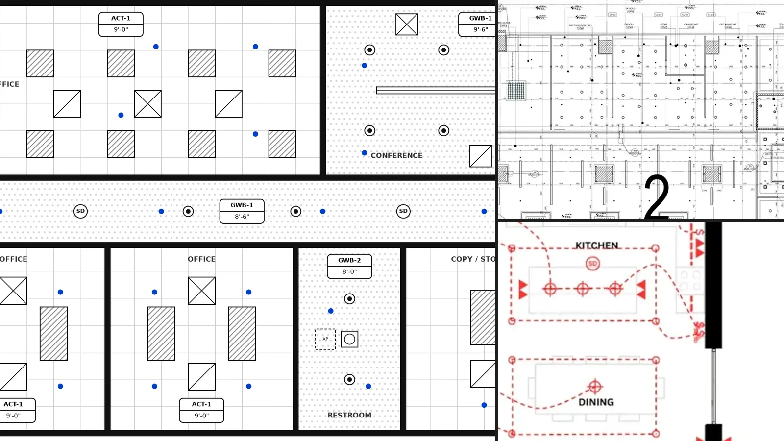
This guide explains why the drawing is reflected, what goes on an RCP, the symbols you will meet, how to read one, and how to draw one in Revit or AutoCAD. We drew a complete example RCP and a symbols legend for it, and there are two real RCPs from practice.
The short version
- Reflected, so it lines up: looking up would flip left and right; the mirror keeps the floor plan's orientation. See the difference.
- It shows the whole ceiling: materials, heights, grid, lights, diffusers, sprinklers, detectors, exit signs. What goes on an RCP.
- Symbols vary by office, so read the legend; ours covers the common ones. RCP symbols.
- Not the same as a lighting plan: the RCP coordinates the ceiling, the lighting plan circuits the lights. RCP vs lighting plan.
- In Revit it is a ceiling plan view of each level; in AutoCAD a copy of the floor plan with the ceiling drawn on it. How to draw one.
What is a reflected ceiling plan?
Reflected ceiling plan (definition): a plan view of the ceiling of one level, drawn as the ceiling's reflection in an imaginary mirror on the floor, so that it shares the floor plan's orientation; it shows ceiling materials, heights and grids and every ceiling-mounted element.
Like a floor plan, an RCP is a horizontal cut through the building. The floor plan cuts about 4 feet above the floor and looks down. The RCP cuts just below the ceiling and shows what is above the cut. Walls that reach the ceiling are drawn cut, as heavy lines. Doors and windows usually disappear, because the cut passes above their heads, so the walls run straight through the openings. Furniture and anything else on the floor is not shown.
RCPs belong to the architectural plans in a drawing set and are drawn at the same scale as the floor plans: commonly 1/8" = 1'-0" (1:100) for larger buildings and 1/4" = 1'-0" (1:50) for houses and interiors. Our guide to architectural drawings shows where the RCP sits among the other sheets of a set.
Why "reflected"?
Imagine lying on your back in the middle of a room, head to the north, looking at the ceiling. East and west are now swapped: what is on your left in the floor plan is on your right above you. A ceiling drawn that way would be flipped against the floor plan, and every light would have to be mirrored back before anyone could check what is under it.
So the convention is to draw the ceiling as it would look reflected in a mirror laid on the floor. The reflection keeps the floor plan's orientation: same north, same grid lines, same left and right. A pendant drawn over the dining table on the RCP sits over the dining table on the floor plan. That is the only thing "reflected" means. The RCP is not mirrored compared with the floor plan; it matches it.
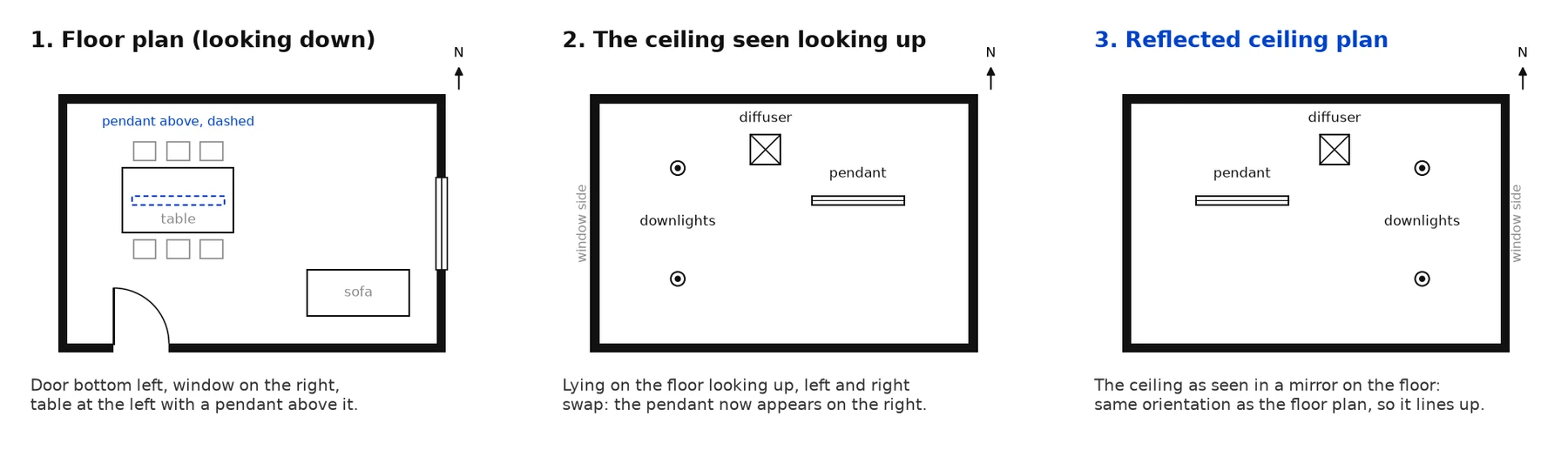
One room three ways. Looking up (2) swaps left and right. The reflected ceiling plan (3) keeps the floor plan's orientation, so the pendant lines up with the table below it. The walls in 2 and 3 are continuous because the RCP is cut above the door and window heads.
What goes on a reflected ceiling plan
A complete RCP for a commercial interior carries:
| Element | What the RCP shows | Who usually decides it |
|---|---|---|
| Ceiling materials | Extent of each ceiling type, keyed to a finish code (ACT-1, GWB-1) | Architect / interior designer |
| Ceiling heights | Height above finished floor (AFF) of each ceiling, often in a tag with the material | Architect |
| Ceiling grid | Layout of the acoustical tile grid and where it starts | Architect |
| Soffits and bulkheads | Dropped areas, coves, steps in the ceiling, with their heights | Architect |
| Light fixtures | Position and type of every fixture: troffers, downlights, pendants, wall washers, linear lights | Architect and electrical engineer / lighting designer |
| Air diffusers and grilles | Supply diffusers, return and exhaust grilles, exhaust fans | Mechanical engineer |
| Sprinkler heads | Positions coordinated with lights and grid | Fire protection engineer / contractor |
| Detectors and devices | Smoke and heat detectors, exit signs, speakers, cameras, Wi-Fi access points | Electrical, fire alarm and low-voltage designers |
| Access panels | Openings to reach valves and equipment above a hard ceiling | Architect with the MEP engineers |
| Skylights and openings | Openings in the ceiling plane | Architect |
| Legend and notes | Symbols, ceiling finish key, general notes such as "all heights AFF" | Architect |
Because so many trades put things in the same few square feet, the RCP is a coordination drawing first. Two classic clashes it catches: a sprinkler head drawn where a light fixture needs to go, and a diffuser that lands half on a tile and half on a grid line. In a BIM model, clash detection between the ceiling, the lights and the ducts above it does the same job in 3D.
Reflected ceiling plan symbols
There is no single national standard for RCP symbols in the US. Offices and engineers use similar but not identical symbols, which is why every RCP has a legend, and the legend on the sheet wins. These are the common conventions, drawn the way we use them in the example below:
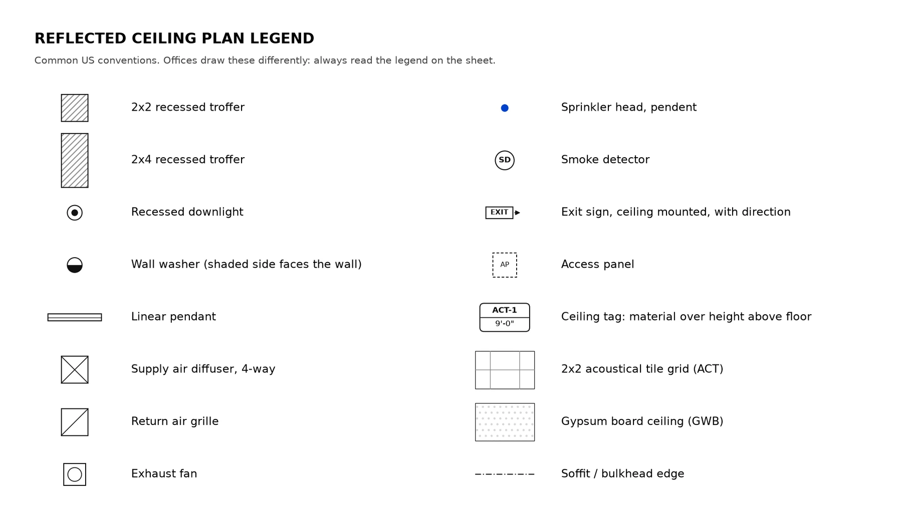
Common RCP symbols. Supply diffusers (both diagonals) and return grilles (one diagonal) are the pair most often confused; the ceiling tag gives the material code over the height above finished floor.
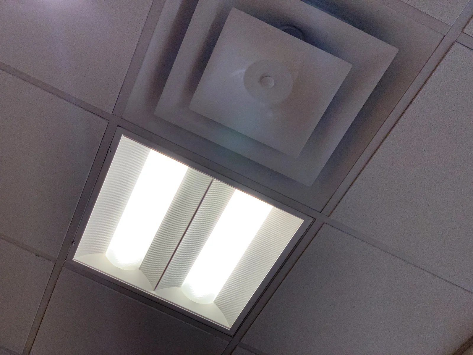
What two of those symbols are on site: a 2x2 recessed troffer (the hatched square) and a square 4-way supply diffuser (the square with both diagonals), each filling one cell of a 2x2 acoustical tile grid. Photo: Office Drop Ceiling HVAC Vents and Lights by Tony Webster, CC BY 2.0, via Wikimedia Commons.
A few reading tips for the symbols:
- Fixture types are tagged, not just drawn. A letter or code beside a fixture (A, B1, L3) points to the light fixture schedule, which gives the exact product, wattage and mounting. Two identical circles can be different fixtures.
- Diffusers often carry a tag too, with the airflow and neck size the mechanical engineer specified, for example a code over "250 CFM".
- Dashed means above or hidden. Dashed outlines show things above the ceiling plane, such as a beam, a duct or the edge of a higher ceiling.
A complete RCP, read step by step
We drew this RCP for a made-up office suite of 48 by 32 feet, with every element from the table above:
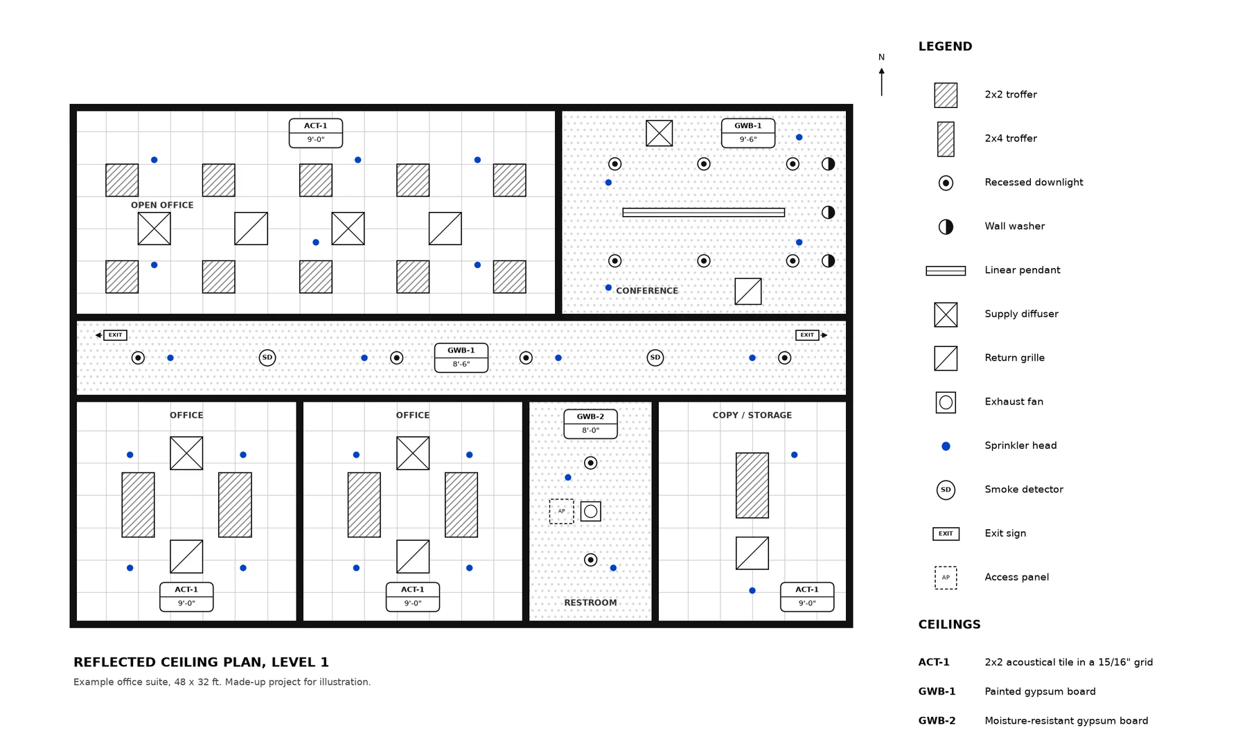
Our example RCP of a made-up office suite. Read the legend first, then the ceiling tags, then the grid, then the fixtures room by room.
Read it in this order:
- Legend and finish key first. ACT-1 is 2x2 acoustical tile in a grid, GWB-1 painted gypsum board, GWB-2 moisture-resistant board for the restroom. All heights are above finished floor.
- Ceiling tags next. The corridor is lower (8'-6") than the offices (9'-0") because the ducts and pipes run above it; the conference room is higher (9'-6"). Each change in height means a soffit or a step where two ceilings meet.
- Then the grid. In each ACT room the grid is centred, so the cut tiles at opposite walls are equal and no border tile is smaller than half a tile. Slivers of tile along a wall look like a mistake, and they are one.
- Then the fixtures, room by room. Troffers sit inside grid cells, not across grid lines. Diffusers and returns alternate between the rows of lights. Sprinklers sit in the gaps, clear of lights and diffusers. In the corridor, smoke detectors and exit signs share the ceiling with the downlights.
- Finally the details and what is missing. The restroom has a hard gypsum board ceiling, so it gets an access panel to reach what is above it; in the ACT rooms you lift a tile instead. There are no doors and no windows: the cut is above their heads, so the walls run through.
RCP vs lighting plan vs ceiling plan
These three get mixed up all the time:
- Reflected ceiling plan (architectural, A-series). The coordination drawing of the whole ceiling: materials, heights, grid, and every device in it, from all trades.
- Lighting plan (electrical, E-series). The engineer's drawing of the light fixtures with fixture types, circuits, switching and controls, usually on a plain background of the RCP. It must match the RCP, fixture for fixture.
- Ceiling plan. In architecture, usually just another name for the RCP. A ceiling framing plan is different: a structural drawing of the joists that hold the ceiling.
On houses, one sheet often does all of it. This student's electrical plan is titled RCP and shows the downlights, pendants and ceiling fans together with the switches, outlets and wiring runs:
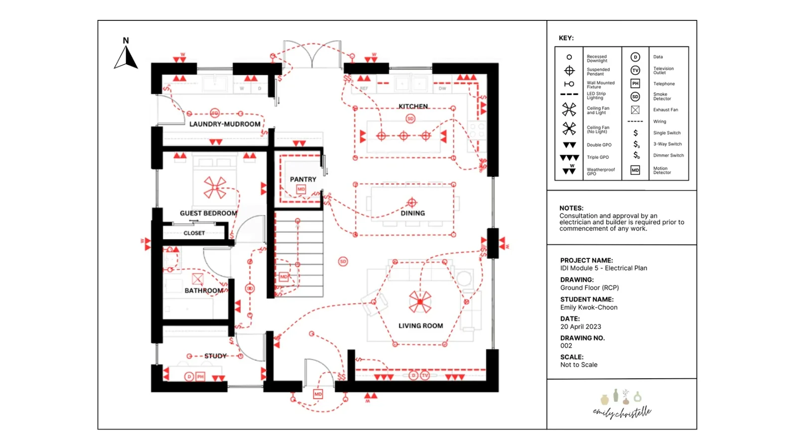
A residential plan combining the RCP and the lighting and power plan: fixtures, switching (the dashed runs) and outlets on one sheet, as is common on houses. On commercial projects these are separate architectural and electrical sheets. Reference: Creating an Electrical Plan by Emily Kwok on Behance.
On large commercial projects the RCP is often split into parts with match lines and drawn again as a contractor's shop drawing, with every ceiling level and fixture dimensioned:
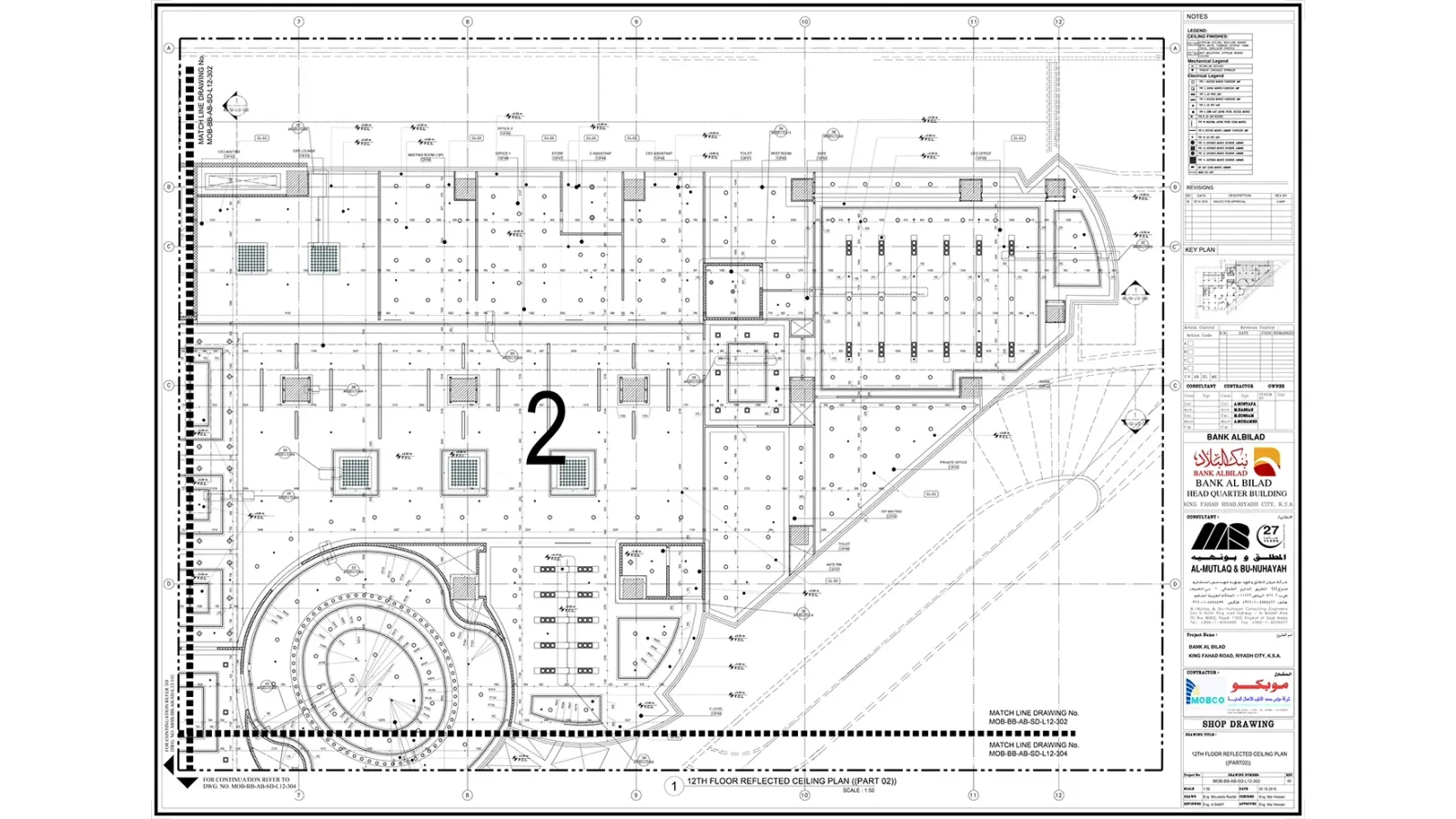
A commercial RCP shop drawing at 1:50, part 2 of the 12th floor: ceiling level tags in every room, separate mechanical and electrical legends in the title block, a key plan, and match lines to the adjoining sheets. Reference: Bank Albilad, 12th floor reflected ceiling plan by Moustafa Raafat on Behance.
How to draw a reflected ceiling plan in Revit
In Revit the RCP is a view of the model, not a separate drawing, which is why it stays in step with the floor plans:
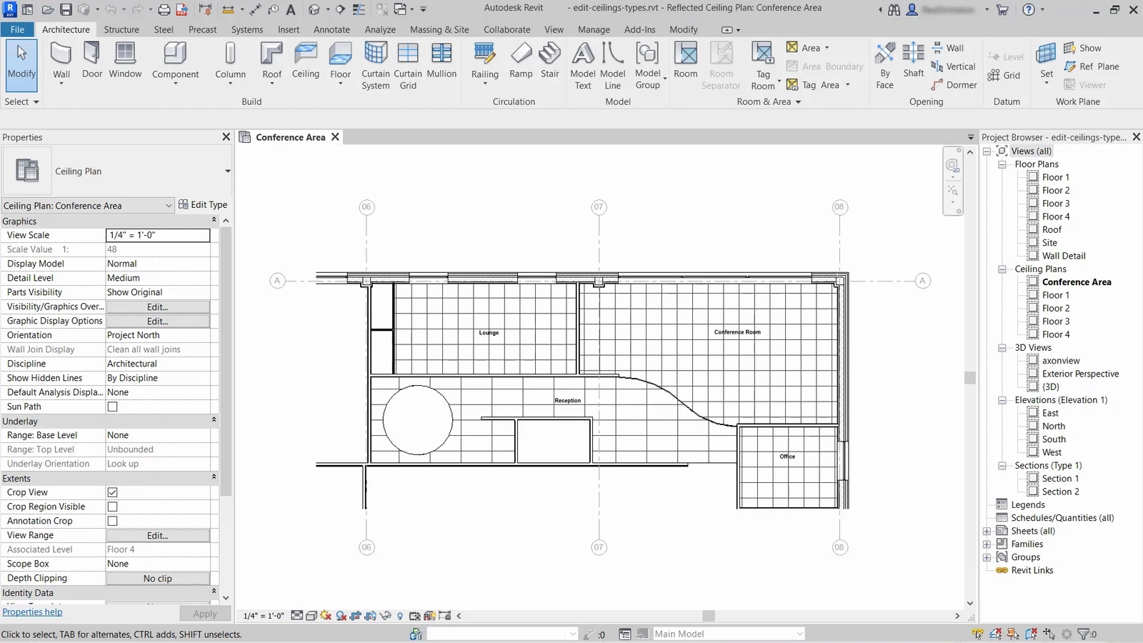
A reflected ceiling plan in Revit: 2x2 ACT grids in each room, the Ceiling Plans listed per floor in the Project Browser, and "Look up" as the underlay orientation in the view's properties. Frame from Autodesk's Create ceiling types and edit ceiling grids tutorial, © Autodesk, CC BY-NC-ND 3.0.
- Open the ceiling plan of the level. When you add a level with a plan view, Revit makes a ceiling plan for it, listed under Ceiling Plans in the Project Browser. You can add more with View > Plan Views > Reflected Ceiling Plan. The view looks up from a cut plane below the ceiling; check its view range if things you expect are missing.
- Draw the ceilings with Architecture > Ceiling. Automatic Ceiling fills a room bounded by walls with one click; Sketch Ceiling lets you draw any outline. Set each ceiling's type (for example a 600 x 600 or 2' x 2' ACT system or gypsum board) and its height offset from the level.
- Set out the grid. Select a grid line and move it, or use Align, to centre the grid in the room; rotate it if the room is not square to the building.
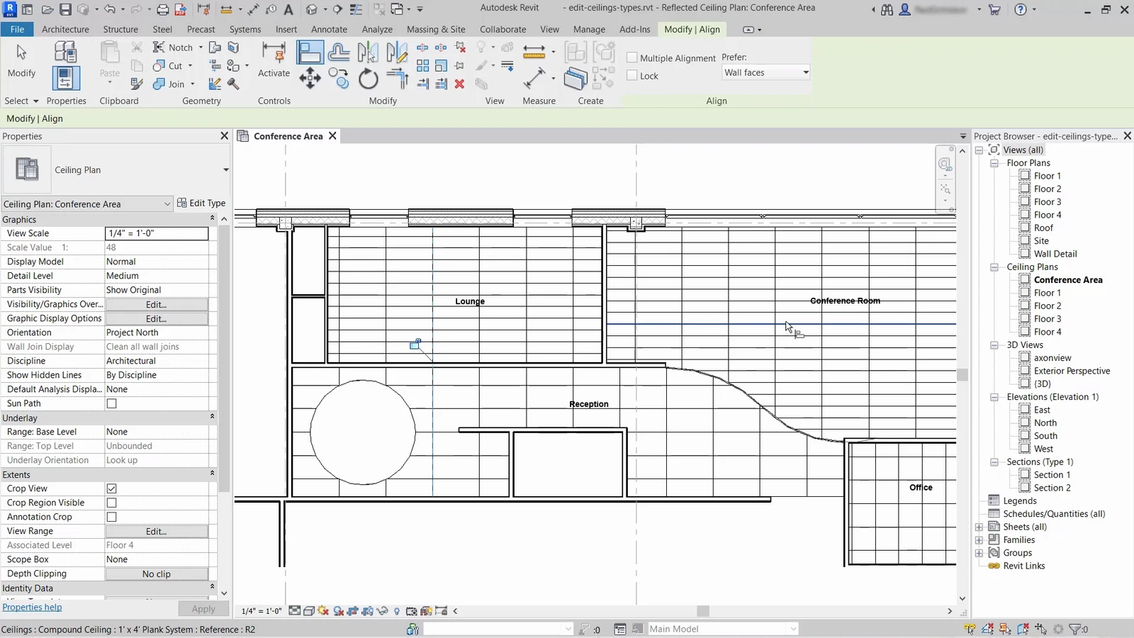
Setting out the grid with Align after the lounge and conference room ceilings were changed to a 1' x 4' plank system. Frame from the same Autodesk tutorial, © Autodesk, CC BY-NC-ND 3.0.
- Place ceiling-hosted families: light fixtures, air terminals, sprinklers, detectors. With linked engineering models, the engineers' lights and diffusers show up in your RCP.
- Tag and annotate. Tag the ceilings (a ceiling tag can show the height), tag fixture types, add a legend view and the finish key, and place the view on a sheet with your title block.
How to draw a reflected ceiling plan in AutoCAD
In AutoCAD the RCP is a separate drawing built on the floor plan:
- Start from the floor plan. Copy the plan, or xref it, and freeze the layers you do not need: doors, door swings, windows, furniture, floor finishes. Close the wall lines through the door openings, since the RCP is cut above them.
- Draw the ceiling areas on a ceiling layer and hatch them by type. For a 2' x 2' ACT grid, use a user-defined hatch with a 2' spacing and the Double option, and set the hatch origin so the grid is centred in the room.
- Insert fixture blocks for lights, diffusers, sprinklers and detectors, one layer per trade, so each consultant can turn the others off.
- Add the ceiling tags, the legend and the notes, and place the drawing on a layout with a title block. Our title block guide shows the layout steps and has free DXF templates.
Common RCP mistakes
- Mirroring the ceiling. Drawing what you see looking up flips it against the floor plan. The RCP should overlay the floor plan exactly.
- Uncentred grids. A grid started from one wall leaves slivers of tile along the other. Centre it, or start it from a feature such as a lighting row, on purpose.
- Fixtures across grid lines. A 2x2 troffer has to sit in a 2x2 cell. Check the grid before placing lights.
- Missing heights. Every ceiling needs a height AFF, and every step between heights needs a soffit detail somewhere in the set.
- Out of step with the engineers. If the RCP shows a downlight where the lighting plan shows a troffer, someone on site will send an RFI. Overlay the RCP with the E and M sheets before every issue.
- Leaving out the devices nobody "owns". Exit signs, speakers, cameras and Wi-Fi access points all land in the ceiling and need space too.
Where AIBIMTool fits
AIBIMTool generates the early BIM model of a building from a written brief and a real site: an editable IFC4 file with storeys, walls, slabs, doors, stairs, a roof and named rooms, plus a 2D plan of every storey. It does not model ceilings, lights or diffusers, so it does not produce an RCP. The RCP comes later, in Revit, Archicad or another BIM tool, once you have opened the IFC model and added the ceilings and the engineers' models.
Start from a model, then draw the ceilings
- Brief and site in, BIM out. AIBIMTool models storeys, walls, slabs, doors, stairs and rooms as IFC4.
- Open it in Revit or Archicad and add ceilings, lights and the ceiling plans there.
- Free to try: one AI generation on the free plan.
Sources
- Autodesk, About the View Range (Revit help): how plan and reflected ceiling plan views are cut.
- Autodesk Learn, Create ceiling types and edit ceiling grids: the Revit screenshots. Photo: Office Drop Ceiling HVAC Vents and Lights, Tony Webster, CC BY 2.0.
- Moustafa Raafat, Bank Albilad 12th floor RCP and Emily Kwok, Creating an Electrical Plan, on Behance: the two real sheets in this article.
Frequently asked questions
What is a reflected ceiling plan?
A reflected ceiling plan (RCP) is an architectural drawing of the ceiling, drawn as if the floor were a mirror reflecting the ceiling above it. It shows ceiling materials and heights, the ceiling grid, soffits, and everything mounted in the ceiling: light fixtures, air diffusers and grilles, sprinkler heads, smoke detectors, exit signs, speakers and access panels. Because it is reflected, it has the same orientation as the floor plan and lines up with it sheet over sheet.
Why is it called a reflected ceiling plan?
Because it shows the ceiling as it would appear reflected in a mirror laid on the floor. If you lay on the floor and looked straight up, left and right would be swapped compared with the floor plan. The mirror trick keeps the drawing in the same orientation as the floor plan, so a light drawn above a table on the RCP sits exactly over that table on the floor plan.
Is a reflected ceiling plan mirrored?
No, not compared with the floor plan. That is the point of reflecting it: an RCP has exactly the same orientation, north arrow and grid lines as the floor plan of the same level. It is only mirrored compared with what you would see standing in the room and looking up.
What is the difference between a ceiling plan and a reflected ceiling plan?
In architecture they usually mean the same drawing, and the ceiling plan in a construction set is drawn reflected. A ceiling seen from below without the mirror convention would be flipped left to right and would not line up with the floor plan, so it is rarely drawn. A ceiling framing plan is something else: a structural drawing of the joists or framing that hold the ceiling up.
What is the difference between a reflected ceiling plan and a lighting plan?
The RCP is the architect's coordination drawing of the whole ceiling: materials, heights, grid, lights, diffusers, sprinklers and detectors. The lighting plan is the electrical engineer's drawing of the light fixtures with their types, circuits and switching, on E-sheets. On commercial projects they are separate sheets that must agree; on houses one sheet often does both jobs.
What should be included in a reflected ceiling plan?
Walls cut just below the ceiling, ceiling materials and their extents, ceiling heights above finished floor, the ceiling grid set out from a starting point, soffits and bulkheads, light fixtures, supply diffusers, return and exhaust grilles, sprinkler heads, smoke and heat detectors, exit signs, speakers, access panels, skylights, a legend of symbols and a ceiling finish key. Doors and windows are usually left out, because the cut is above their heads.
How do you create a reflected ceiling plan in Revit?
Revit creates a ceiling plan view for each level, under Ceiling Plans in the Project Browser, and you can add more from View > Plan Views > Reflected Ceiling Plan. The view looks up from a cut plane below the ceiling. Draw ceilings with the Ceiling tool, set each one's height offset from the level, move and align its grid, place ceiling-hosted lights and air terminals, then tag the ceilings and add a legend.
What scale is a reflected ceiling plan drawn at?
The same scale as the floor plan of that level, so the two can be compared and overlaid: commonly 1/8 inch = 1 foot (1:100) for larger buildings and 1/4 inch = 1 foot (1:50) for houses and interiors. Complex ceilings can get enlarged RCPs at a larger scale.







Architectural Drawings: 12 Types, Scales and How to Read Them
What architectural drawings are, the 12 types in a full drawing set with real examples, US scales, sheet numbers like A-101, the drawings each project phase produces and how to read them.
Title Block: What It Is, What Goes in It, and Free Templates (DXF, PDF)
What a title block is, the fields every drawing sheet needs, where it goes on US and ISO sheets, real examples, how to add one in AutoCAD and Revit, and five free title block templates as DXF and PDF.
IFC Drawings: What Issued for Construction Means, and IFC vs IFA, IFB and Shop Drawings
IFC drawings are the sheets issued for construction: the revision a contractor is allowed to build from. What an IFC set contains, the IFR, IFA, IFB, IFC ladder, how IFC differs from shop and as-built drawings, how revisions work after issue, and the UK ISO 19650 codes that replace it.