
MEP Meaning in Construction: What Mechanical, Electrical and Plumbing Covers

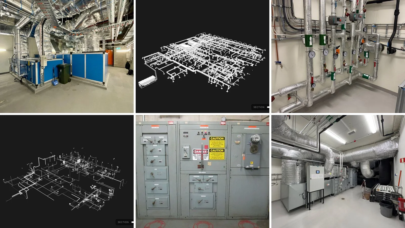
MEP stands for mechanical, electrical and plumbing. In construction it means the systems that heat, cool and ventilate a building, bring it power and light, and supply and drain its water. MEP is designed by engineers, installed by specialist trade contractors, and in a building model it is usually the part with the most components and the most coordination work.
Our articles are still written by humans!
Get human written articles in your Google feed.
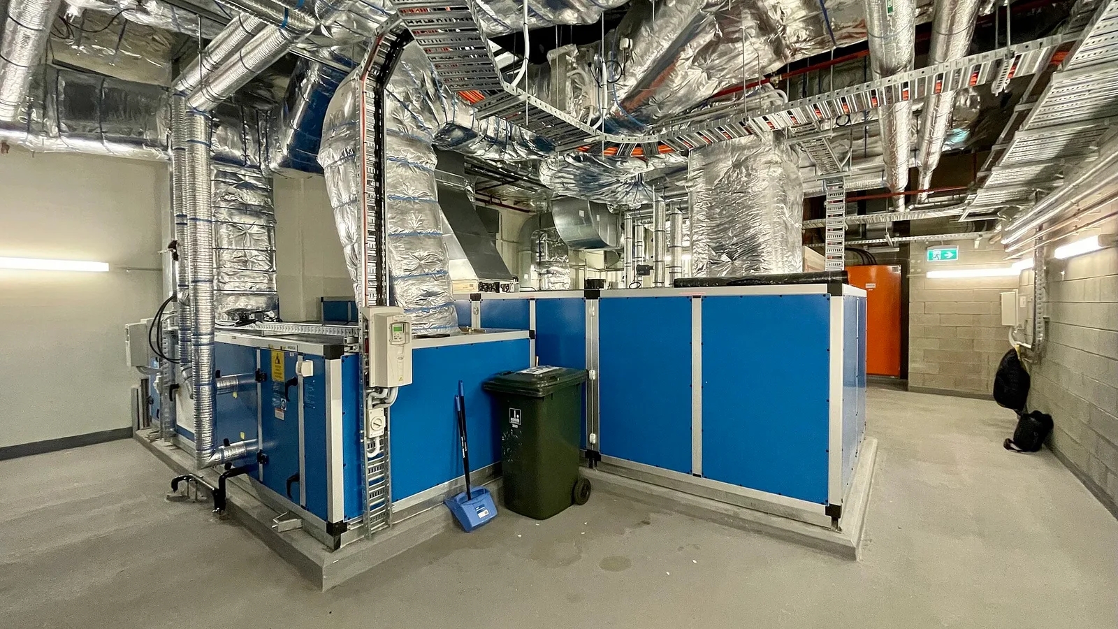
All three letters in one room: air handling units (M), cable trays (E) and insulated pipework (P and M) in a commercial building in Brisbane. Photo: Air handling units in large commercial building, Brisbane by Kgbo, CC BY-SA 4.0, via Wikimedia Commons.
To put a number on "most components", we counted every element in the five discipline models of a real two-storey clinic. The ducts, pipes, fittings, fixtures and devices came to 12,409 of 16,116 elements, or 77%. That count is in the section on size, after the definitions.
What each letter covers
The three letters are a contractor's and an engineer's shorthand, not a formal standard, so the edges move from project to project. The table uses the two US references that do draw lines: the sheet prefixes of the National CAD Standard and the divisions of CSI MasterFormat.
| What it covers | Sheet prefix | MasterFormat division | |
|---|---|---|---|
| M, mechanical | Heating, ventilation and air conditioning: boilers, chillers, heat pumps, air handling units, ducts, diffusers, hydronic pipework, controls | M | 23 HVAC, 25 Integrated Automation |
| E, electrical | Incoming service, switchgear, panels, feeders, lighting, sockets, earthing, emergency power | E | 26 Electrical |
| P, plumbing | Domestic hot and cold water, sanitary drainage and vents, storm drainage, gas, fixtures | P | 22 Plumbing |
| Fire protection | Sprinklers, standpipes, fire pumps | F | 21 Fire Suppression |
| Low voltage | Data, telephone, fire alarm, access control, CCTV | T (and E) | 27 Communications, 28 Electronic Safety and Security |
Two rows are not in the acronym. Fire protection and low-voltage systems are almost always coordinated with MEP, often by the same engineering firm, yet each has its own sheets and its own specification division. A firm that wants to be explicit writes MEPF or MEP/FP.
Elevators are the usual wrong guess. They are conveying equipment (Division 14), supplied and installed by the manufacturer, and the MEP trades only serve them with power, ventilation and a pit sump.
The term is American. In the UK the same field is called building services, or M&E with public health engineering for the plumbing side. German uses TGA, short for Technische Gebäudeausrüstung.
M is mostly HVAC
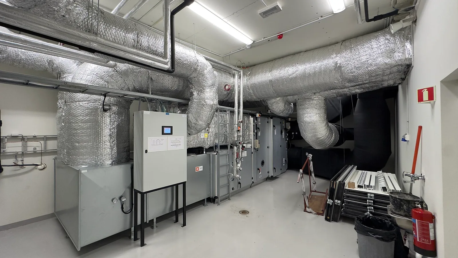
Mechanical room of a school in Lillehammer, Norway, September 2024: air handling unit, insulated ducts and the control cabinet. Photo by Wolfmann, CC BY-SA 4.0, via Wikimedia Commons.
When people say "the mechanical", they nearly always mean heating, ventilation and air conditioning. The mechanical engineer calculates how much heat each room loses and gains, picks the plant that covers it, and routes air and water from that plant to every room. Ducts are the bulky part. A main supply duct can be deeper than the beam it has to pass under, which is why the mechanical layout decides ceiling heights more often than the architect would like.
E runs from the utility to the socket
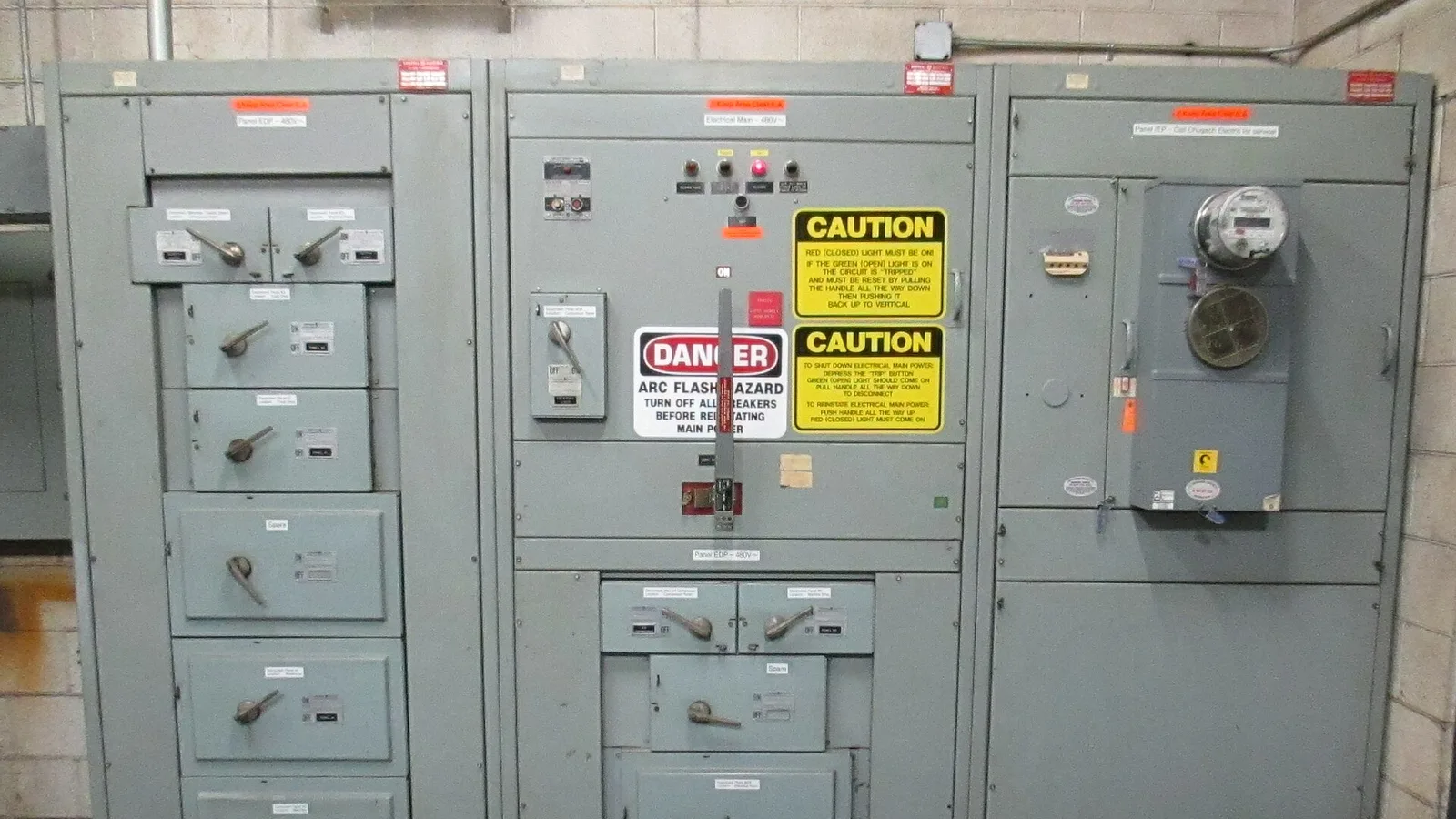
A 480 volt main and distribution panel in a large facility. Photo: Electrical Main and distribution panel for 480 volt by Zaereth, CC BY-SA 4.0, via Wikimedia Commons.
Electrical starts at the utility connection and ends at the last light fitting. In between are the main switchgear, transformers, distribution panels, the feeders that link them, and the branch circuits to lighting and power. Standby generators and uninterruptible power supplies belong here too. Electrical usually takes the least space of the three, but it touches every room and every piece of mechanical and plumbing equipment that has a motor.
P is water in, waste out
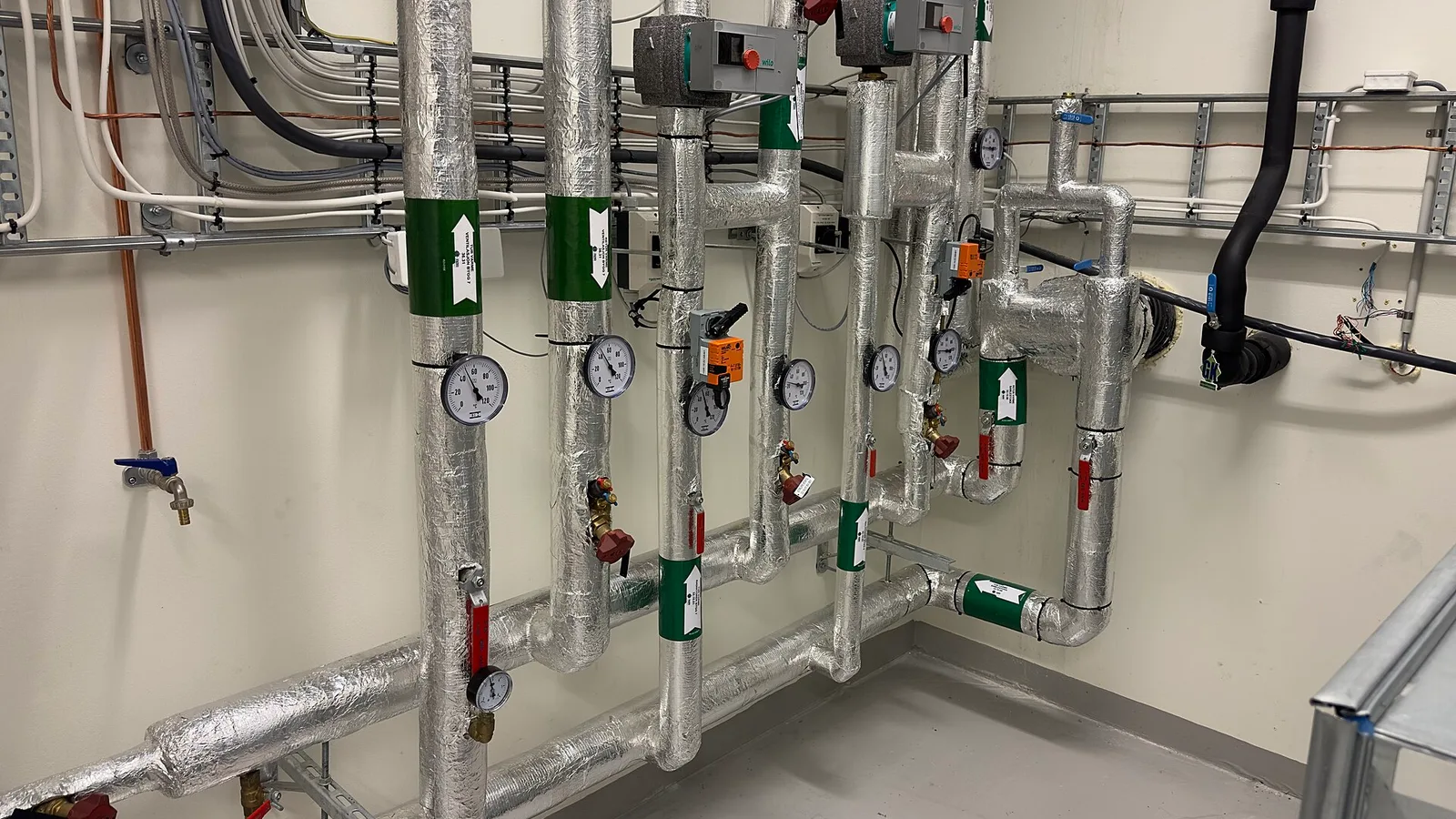
Insulated pipework with gauges and motorised valves in the same school. These are heating circuits, which the mechanical engineer designs, although a pipefitter installs them. Photo by Wolfmann, CC BY-SA 4.0, via Wikimedia Commons.
Plumbing covers domestic cold and hot water, the sanitary drainage and its vent pipes, rainwater, and gas. The detail that catches out newcomers is that pipe alone does not make something plumbing. Chilled water and heating pipes are mechanical. Sprinkler pipes are fire protection. Plumbing is the water people use and the waste they produce.
Drainage also has the least freedom of any system in the building, because it runs by gravity at a fixed fall. When a drain and a duct want the same space, the duct moves.
How much of a building is MEP?
Most articles answer this with a cost percentage. We will come to cost, but first a count that can be checked.
buildingSMART publishes a set of test models of a two-storey medical and dental clinic, a real building with its identifying details removed, under a CC BY 4.0 licence. It comes as five IFC files, one per discipline, exported from Revit. On 12 November 2026 we opened each file in our free IFC viewer and counted the physical elements with a short script. Openings, rooms and connection ports were left out.
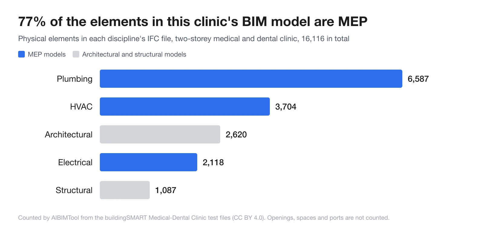
Element counts from the buildingSMART Medical-Dental Clinic test files, counted by AIBIMTool on 12 November 2026.
| Discipline model | Elements | File size |
|---|---|---|
| Plumbing | 6,587 | 55.8 MB |
| HVAC | 3,704 | 26.9 MB |
| Architectural | 2,620 | 13.0 MB |
| Electrical | 2,118 | 6.8 MB |
| Structural | 1,087 | 19.1 MB |
| MEP share | 12,409 of 16,116 (77%) | 89.5 of 121.6 MB (74%) |
The architect's model has 269 rooms. That works out at 46 MEP elements for every room in the building.
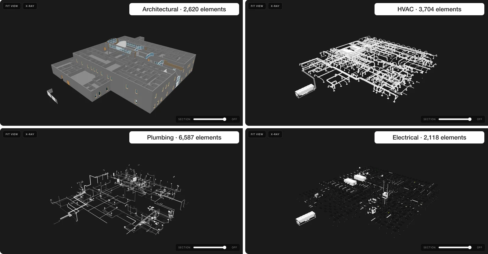
One clinic, four of its five files, each opened in the AIBIMTool IFC viewer. Model: Medical-Dental Clinic test files, buildingSMART International, CC BY 4.0.
Five details in the files say more than the headline number.
- The plumbing model holds more fittings than pipes: 3,318 fittings against 2,893 straight segments. Every elbow, tee and reducer is its own object, each with a position that can clash with something.
- 1,476 plumbing elements, 22% of that model, are assigned to the footing level under the ground floor. That pipework is cast in or buried before the slab is poured, so it is the first MEP work on site and the hardest to correct later.
- The HVAC model is 1,509 ducts, 1,590 duct and pipe fittings, 440 diffusers, registers and grilles, and 115 VAV units. That is one VAV box for every two or three rooms.
- The electrical model contains 961 duplex receptacles, 236 light switches, 28 panelboards and several hundred light fittings, and not one cable, conduit or cable tray. Wiring is rarely modelled, so an electrical model shows where things are and almost nothing about how they are connected.
- Class names cannot be trusted blindly. The architectural file has 102 objects exported as "flow terminals", a class meant for MEP. By name they are 44 grab bars, 22 towel dispensers, 22 mirrors, 10 fire extinguisher cabinets, three shower seats and an elevator. We left them in the architect's total.
The pattern is the same in the smaller Duplex Apartment test set from the same source: 926 elements in the combined MEP file against 218 in the architectural one.
A count is not a cost. A wall and a pipe elbow each count as one element, and the wall is worth far more. What the count measures is coordination load: how many separate objects have to be placed, sized and kept out of each other's way.
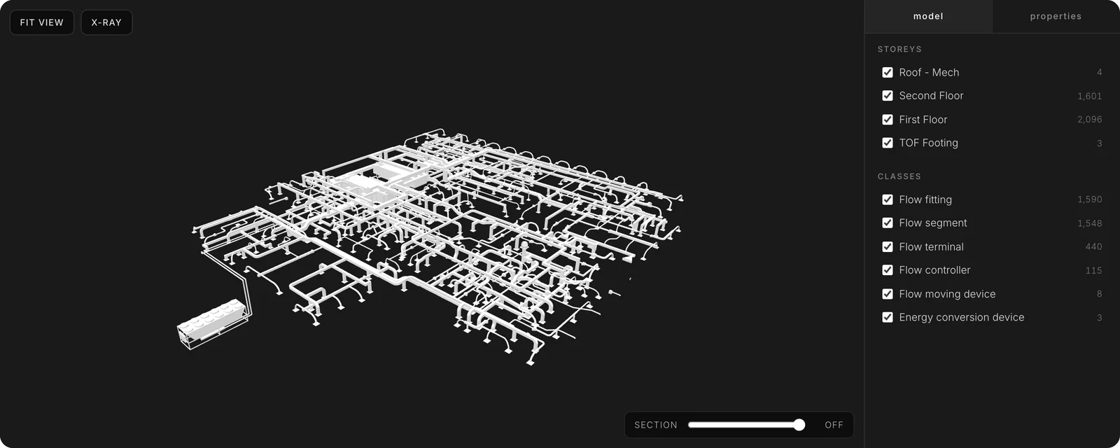
The clinic's HVAC file in the AIBIMTool IFC viewer. The class list on the right is where the counts above can be read without any script.
What about cost?
Articles put MEP anywhere from 15% to 60% of construction cost. We looked for the dataset behind those ranges and could not trace them to a public one, so we are not going to repeat a figure as fact. The direction is not in doubt. A warehouse has little MEP, an office has more, and hospitals, laboratories and data centres have the most, because the share follows how much air, power and piped services each square metre needs.
A number that can be verified is employment. The US Bureau of Labor Statistics counts the people on construction payrolls every month, by type of contractor.
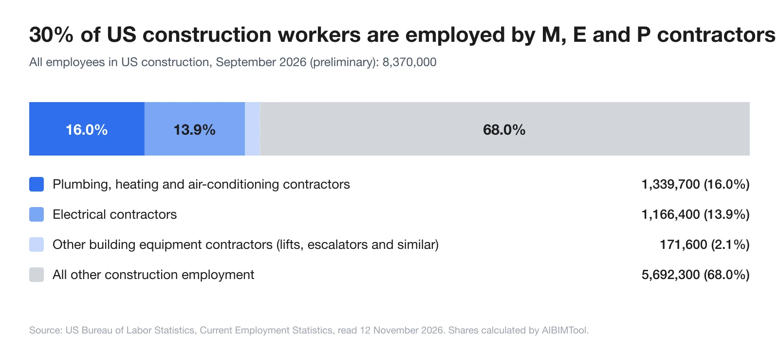
US Bureau of Labor Statistics, Current Employment Statistics, September 2026 (preliminary, seasonally adjusted), read on 12 November 2026. Shares are our calculation.
In September 2026, plumbing, heating and air-conditioning contractors employed 1,339,700 people and electrical contractors 1,166,400. Together that is 2,506,100 of 8,370,000 construction employees, or 30%. Counted against specialty trade contractors only, it is 47%.
Read it with two limits in mind. These payrolls include service and repair work in existing buildings, such as replacing a boiler, so the figure describes the trades and not new projects alone. And MEP design engineers are not in it at all, because the statistics file them under engineering services.
Video: what MEP is and how to manage it on site
What Is MEP In Construction?, by Jason Schroeder on YouTube, 9 minutes 6 seconds, published 12 March 2024. The player only loads when you press play.
We picked this one because it is about running MEP on a project, not about engineering theory. The chapter from 2:24 covers how to think of MEP as systems, the one from 4:00 how to picture the connections between them, and from 4:47 Schroeder gives his tips for managing the installation.
MEP drawings: the M, E and P sheets
MEP drawings are the sheets of a construction set that show these systems. In a US set numbered to the National CAD Standard, each sheet number starts with the discipline letter, then a digit for the sheet type, then a sequence number. M-101 is the first mechanical plan and E-601 is the first electrical schedule or diagram sheet.
The set is not bound in M, E, P order. The standard's sequence puts fire protection (F) and plumbing (P) ahead of mechanical (M), then electrical (E), then telecommunications (T), all of them after the structural and architectural drawings.
| Discipline | Typical sheets |
|---|---|
| Mechanical | Duct plans, piping plans, equipment schedules, control diagrams, sections through plant rooms |
| Electrical | Lighting plans, power plans, the one-line diagram, panel schedules, riser diagram |
| Plumbing | Water plans, waste and vent plans, riser diagrams, fixture schedule |
The diagram sheets are the quickest way into a set you have never seen. An electrical one-line diagram shows the whole distribution on a single sheet, from utility to panels. A plumbing riser diagram does the same for the pipework, floor by floor. Read those before the plans.
MEP also appears on the architect's sheets. Diffusers, light fittings and sprinkler heads are drawn on the reflected ceiling plan, which is where the three trades and the ceiling grid are made to agree. Every MEP sheet carries the same title block as the others, and the sheets the contractor builds from are those issued for construction.
Who does what
The MEP engineer designs the systems. That means load calculations, equipment selection, the layouts and the specification. One person is a mechanical or an electrical engineer; the firm is the MEP engineer. In the US the drawings are sealed by a licensed Professional Engineer.
MEP contractors install them. There are usually three or four separate subcontractors on a commercial job: mechanical, electrical, plumbing and fire protection. Each produces shop drawings, the fabrication-level versions of the engineer's design showing real products at real sizes.
The MEP coordinator makes the trades fit in the same ceiling. On a BIM project this is the person who combines the models and runs the clash tests, a role we compare with its neighbours in BIM manager vs BIM coordinator.
The gap between engineer and contractor is where most MEP trouble starts. Design drawings show intent, often as single lines with sizes noted beside them. The space those lines need once they become insulated pipe with hangers and access for valves is worked out later, by different people.
MEP in BIM: where the clashes are
With three quarters of the model's objects, MEP is what clash detection is mostly about: duct against beam, pipe against duct, cable tray against sprinkler main. Finding those collisions on screen, before they are found on a scissor lift, is one of the main reasons contractors pay for BIM.
The workflow is the same on most projects. Each trade models its own system, usually in Revit, where the MEP tools have been part of the single Revit product for years (what Revit costs). The models are exported to IFC or combined in Navisworks as an NWD file. A clash test lists the collisions. Each one is assigned to a trade and tracked, in a BCF file or as an RFI when the answer needs the designer, until the list is empty.
Two details from the clinic files explain how MEP looks inside IFC. In the older IFC 2x3 schema a duct and a pipe are both an IfcFlowSegment, and you tell them apart by their type. IFC4 added separate classes such as IfcDuctSegment, IfcPipeSegment and IfcCableCarrierSegment. And how much detail a model needs before a clash test means anything is a level of development question: the BIMForum specification ties coordination to LOD 350, the level that adds the interfaces between systems, such as supports and connections (LOD explained).
Where our own tools fit, and where they stop
AIBIMTool does not design MEP. It generates the architectural model from a written brief and a site: storeys, walls, slabs, doors, stairs and named rooms with areas, exported as IFC4. We checked the models on our own test server before writing this, and none contains a duct, a pipe or a cable tray.
What that model gives an MEP engineer is the starting geometry. The room list with areas is the input for load calculations, and the generator can reserve plant rooms, risers and lift shafts as named rooms, so the space for services is on the plan from the first version instead of being taken out of a tenant's floor later. The engineer then links the IFC in Revit and models the systems there. The free plan includes one AI generation in the 3D viewer; IFC download starts with the paid plans at €49 a month billed yearly.
Two free tools are useful on the MEP side as they are. The IFC viewer opens a consultant's MEP file in the browser with no upload and lists every class with its count, which is how the screenshots above were made. The BCF viewer opens the clash issues a coordinator sends, with their viewpoints, without a Navisworks or Solibri licence.
Give the MEP engineer a model on day one
- AIBIMTool turns a brief and a real site into an IFC4 model with storeys, named rooms and areas, including plant rooms and risers.
- It opens in Revit, where the engineer adds the systems. One AI generation is free; IFC download from €49 a month billed yearly.
Sources
- BSI (2020), Medical-Dental Clinic Test Files and Duplex Apartment Test Files, buildingSMART International, CC BY 4.0: the IFC 2x3 models counted in this article. We changed nothing in the files.
- US Bureau of Labor Statistics, Current Employment Statistics: series CES2000000001 (construction), CES2023800001 (specialty trade contractors), CES2023821001 (electrical contractors), CES2023822001 (plumbing, heating and air-conditioning contractors) and CES2023829001 (other building equipment contractors), September 2026, read 12 November 2026.
- United States National CAD Standard: discipline designators, sheet type digits and the order of disciplines in a set.
- CSI MasterFormat: Divisions 14, 21, 22, 23, 25, 26, 27 and 28.
- buildingSMART, IFC4 Add2 TC1 specification: the distribution element classes for ducts, pipes and cable carriers.
- Jason Schroeder, What Is MEP In Construction?, YouTube, 12 March 2024.
Frequently asked questions
What does MEP stand for in construction?
MEP stands for mechanical, electrical and plumbing. Mechanical is mostly heating, ventilation and air conditioning. Electrical is power distribution, lighting and the low-voltage systems. Plumbing is domestic water, drainage, storm water and gas. Together they are the systems that make a finished shell usable.
Is HVAC part of MEP?
Yes. HVAC is the largest part of the M in MEP. On US drawing sets it sits on the M sheets, and in CSI MasterFormat it is Division 23. Mechanical can also cover building automation and, on some projects, process piping.
Is fire protection part of MEP?
Usually it is managed with MEP but written separately. Sprinklers have their own sheet prefix (F) in the US National CAD Standard and their own MasterFormat division (21). When a firm wants to be explicit it writes MEPF or MEP/FP.
What is an MEP engineer?
An MEP engineer designs the building's mechanical, electrical or plumbing systems: sizes the equipment, lays out the ducts, pipes and circuits, and produces the drawings and specifications. In practice one person is a mechanical engineer or an electrical engineer, and the MEP firm employs both. In the US the drawings are sealed by a licensed Professional Engineer.
What are MEP drawings?
MEP drawings are the sheets of a construction set that show the mechanical, electrical and plumbing systems. Under the US National CAD Standard they carry the prefixes M, E and P, with fire protection on F sheets and telecommunications on T sheets. Each discipline has plans, schedules, diagrams and details.
What is MEP called in the UK?
In the UK the usual term is building services, and the engineer is a building services engineer. M&E, for mechanical and electrical, is also common, with public health engineering covering what Americans call plumbing. In German the field is TGA, Technische Gebäudeausrüstung.
Are elevators part of MEP?
Not normally. Elevators and escalators are conveying equipment, Division 14 in MasterFormat, and are bought from a specialist. They need power, ventilation and a sump from the MEP trades, and US labour statistics group their installers with building equipment contractors, which is why some figures for MEP include them.
What software is used for MEP design?
Most MEP models are built in Revit, which has included its MEP tools in the one Revit product for years, or drafted in AutoCAD with the MEP toolset. Models are exchanged as IFC and checked for clashes in Navisworks or Solibri. AIBIMTool sits before that step: it generates the architectural IFC model with rooms, plant rooms and risers, and it does not draw ducts or pipes.







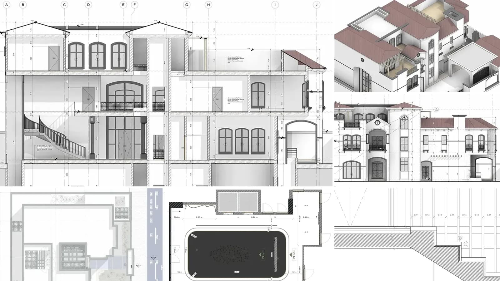
Architectural Drawings: 12 Types, Scales and How to Read Them
What architectural drawings are, the 12 types in a full drawing set with real examples, US scales, sheet numbers like A-101, the drawings each project phase produces and how to read them.
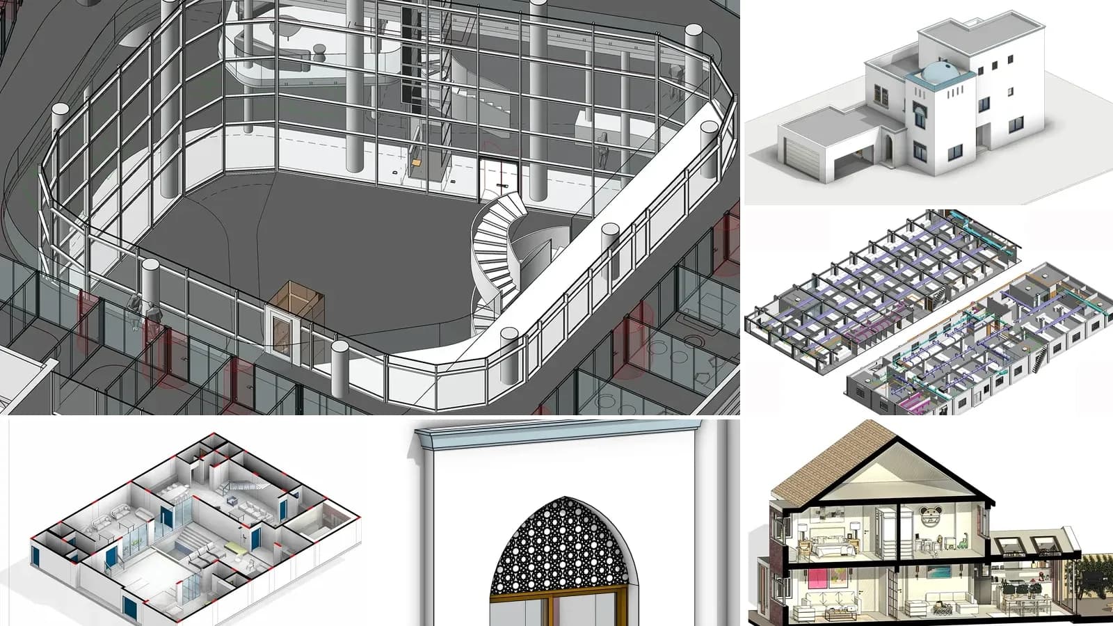
LOD in BIM: Level of Development 100 to 500, Explained with Real Models
LOD in BIM is the Level of Development of each model element, from LOD 100 to 500. What every level means in the 2025 BIMForum spec, LOD vs level of detail and LOIN, and the LOD our own AI-generated models reach.
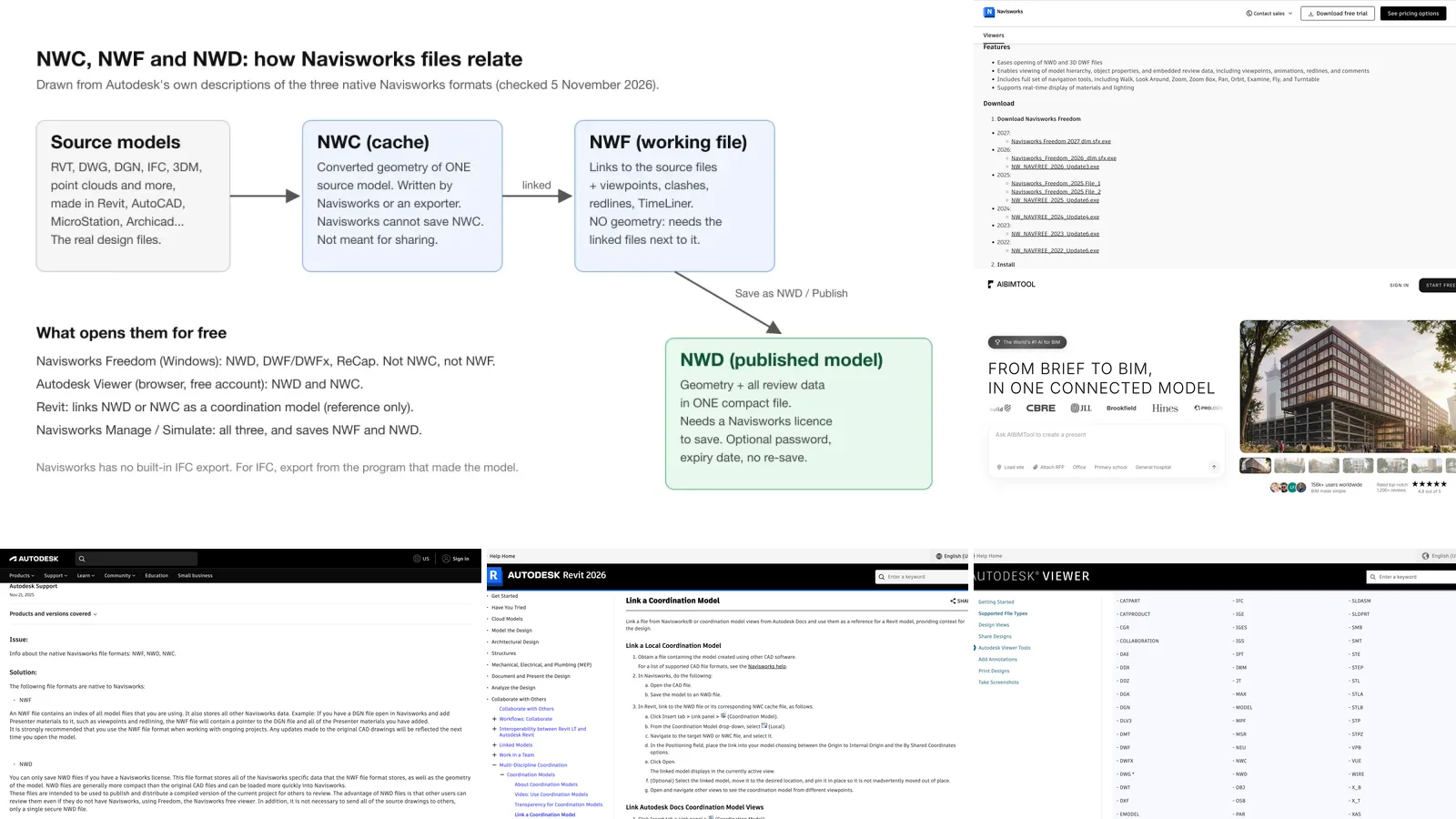
NWD File: What It Is, How to Open It Free, and NWD vs NWC vs NWF
An NWD file is a published Navisworks model: the geometry of every appended model plus viewpoints, clashes and redlines in one compact file. How to open it for free on Windows, on a Mac and in Revit, how it differs from NWC and NWF, why it will not open, and why you cannot turn it into IFC. Checked on Autodesk's own pages.